To achieve the cutting accuracy of the slitting machine ± 0.1mm or even higher, it is necessary to optimize from multiple dimensions such as mechanical design, motion control, tool technology, and environmental management. The following is an in-depth analysis of key technologies and implementation paths:
1. Precision mechanical structure design
1. High rigidity fuselage structure
◦ Cast iron or alloy steel frame with finite element analysis (FEA) to optimize the structure and reduce vibration during high-speed operation (e.g., amplitude control within ±5 μm).
◦ Case: Japan's Asahi Seiki slitting machine adopts a double-layer shock-absorbing platform, which reduces the cutting vibration by 60%.
2. Ultra-precision guidance system
◦ Linear guide rails (e.g., THK Class C guides) with preloaded ball screws, repeat positioning accuracy ≤± 0.005mm.
◦ Air flotation guide rail (used for optical film slitting) to avoid micron-level deviations caused by mechanical contact friction.
2. The core motion control technology
1. Multi-axis servo synchronous control
◦ Servo system (e.g., Beckhoff) with EtherCAT bus communication, the control cycle is ≤1ms, and the synchronization error of the winding shaft, cutter shaft and feeding shaft is <0.01mm.
◦ Algorithm optimization: Feedforward suppresses tracking error during acceleration and deceleration.
2. Closed-loop tension control
◦ Full closed-loop tension sensor (e.g. Sartorius) + magnetic particle clutch with a tension fluctuation ≤± 0.5 N (critical for very thin materials such as 6 μm copper foil).
◦ Segment control: Dynamically adjust the tension curve for changes in the elastic modulus of the material (e.g., PET film from the core to the outside of the roll).
3. Extreme optimization of the tool system
1. Tool material and coating
◦ Diamond-coated round knives (service life of more than 2000 km) or ceramic blades (hardness HV2000) with a roughness of Ra ≤0.2 μm.
◦ Special design: Negative rake angle tools (e.g. -15°) reduce material distortion during cutting.
2. Dynamic balancing of the tool
◦ G1 dynamic balance (residual unbalance< 0.1g·mm/kg), the vibration value < 0.5 μm at the speed of the tool shaft > 3000rpm.
◦ Case: Hydraulic clamping toolholder of German Arntz slitting machine with radial runout ≤±0.003mm.
4. Intelligent detection and real-time compensation
1. On-line measurement system
◦ Laser rangefinder (e.g., Keyence IL series) monitors the width of the material in real time with a resolution of 0.001mm, and adjusts the position of the toolholder with feedback.
◦ Machine vision (5 million pixel CCD) detects edge burrs and triggers tool fine-tuning (response time < 10ms).
2. Temperature compensation technology
◦ Ambient temperature control (±1°C) + scale temperature compensation (e.g. Heidenhain) eliminates positioning drift due to thermal expansion (approx. 12 μm/m per °C steel expansion).
5. Material treatment and process adaptation
1. Expert database of slitting parameters
◦ Presets for different materials (e.g. aluminum foil vs. nonwovens):
◦ Blade overlap (0.01~0.1mm)
◦ Feed rate (usually 50 m/min for copper foil and 150 m/min for diaphragm)
2. Special process assistance
◦ Frozen slitting: -20°C cold air is used to cool down sticky materials (such as medical tape) to prevent the material from sticking to the knife.
◦ Static Elimination: The ionic air bar eliminates the static electricity of the film and avoids the adsorption of debris affecting the accuracy.
6. Typical industry accuracy benchmarking
| industry | Accuracy requirements | Implementation difficulties | solution |
| Lithium electrode sheets | ±0.05mm | Metal ductility leads to burrs | Ultrasonic-assisted cutting + in-line burr detection |
| Optical film | ±0.03mm | Edge transmittance consistency | Air flotation guide rail + sapphire material knife |
| FPC circuit board | ±0.02mm | Risk of layering of multi-layered materials | Laser slitting (ultrafast laser with a pulse width of 10ps) |
Example of implementation path (taking lithium battery separator slitting as an example)
1. Equipment selection: servo motor (Yaskawa Σ-7 series) + high-precision encoder (23-bit resolution).
2. Process commissioning:
◦ Tension setting: 5N for winding, 8N for unwinding (dynamically adjusted according to the elastic modulus of the diaphragm).
◦ Tool angle: Rear angle 12°, overlap 0.05mm.
3. Verification Criteria:
◦ Detect the incision with an electron microscope (1000x) with a burr height of ≤2 μm.
◦ Accuracy attenuation ≤± 0.01mm after slitting 100km (tools need to be replaced regularly).
Future breakthrough direction
• Quantum sensing: Nanoscale displacement sensors, such as the National Physical Laboratory prototype in the UK, enable atomic-scale monitoring.
• Digital twin: Predict accuracy deviations in advance through virtual commissioning (e.g. Siemens Process Simulate can reduce commissioning costs by up to 30%).
The essence of high-precision slitting is the system engineering of "mechanical limit + intelligent compensation", with the integration of precision manufacturing and AI technology, ±0.01mm level accuracy will become the focus of competition for the next generation of slitting machines.

This article will provide an in-depth analysis of the two core pillars of high-precision solar film slitting machines: tension control and closed-loop correction.
06. July, 2026
This article will analyze from four aspects: error sources, the advantages of servo control, key technical implementations, and practical benefits.
25. May, 2026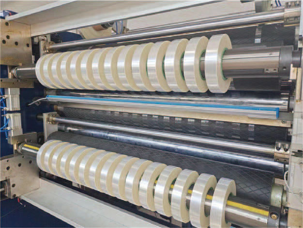
This article will take you through three key steps to easily lock in a high-precision slitting solution.
13. May, 2026
This article will provide an in-depth analysis of the key technologies and challenges involved in achieving high-precision narrow strip slitting in hot stamping foil slitting machines.
21. March, 2026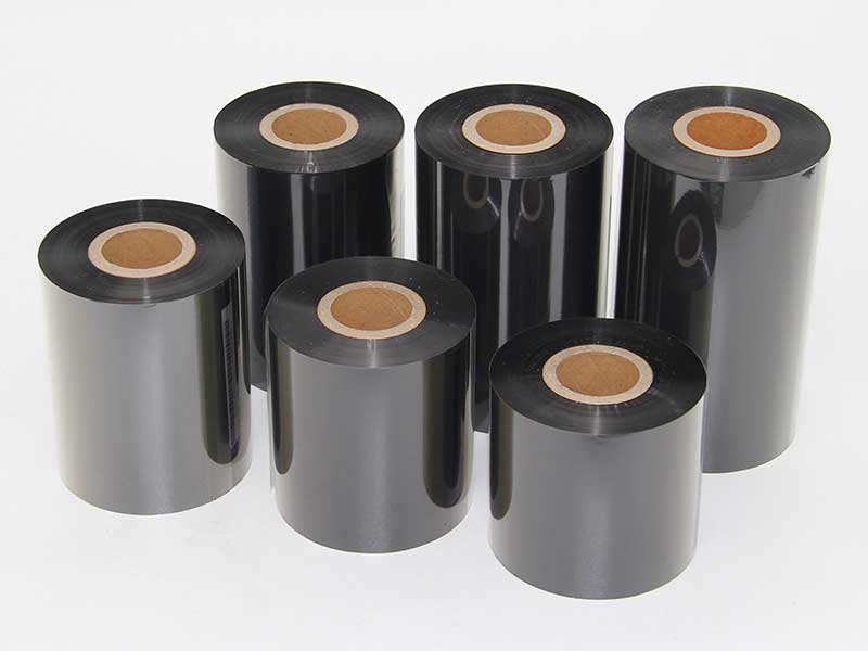
This article will provide an in-depth analysis of the classification and selection points of high-precision ribbon slitting machines.
20. March, 2026


