introduction
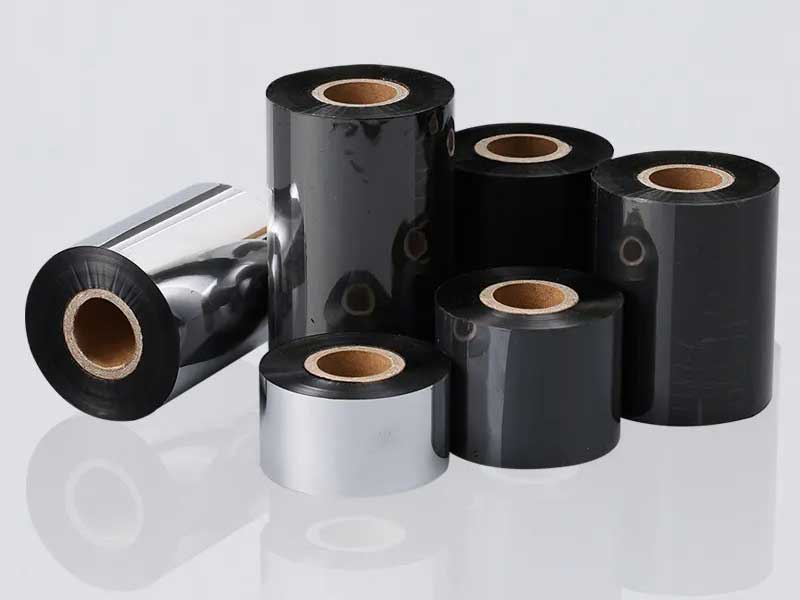
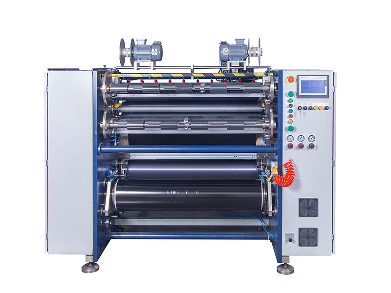
Ribbon slitting machines are the core equipment of labeling, barcode printing and other industries, and their reliability directly affects the quality of the final product (such as carbon-free carbon paper, barcode ribbon, etc.), production efficiency and operating costs. An unreliable slitting machine can lead to problems such as poor slitting accuracy, burrs, broken belts, and frequent downtime. This paper systematically expounds the whole process practice of improving the reliability of ribbon slitting machine from four levels: mechanical structure optimization, electrical control upgrade, intelligent algorithm application and operation and maintenance management.
1. Optimization of Mechanical Structure Reliability: The Cornerstone of Stability
Mechanical structure is the physical basis for equipment reliability, and the optimization of any control system is built on a stable mechanical platform.
1. The rigidity of the frame and base is reinforced
◦ Problem: Lightweight or insufficiently rigid racks are prone to vibration and deformation under high-speed operation and dynamic tension, causing slitting blades to shake and produce burrs.
◦ Optimization Practices:
▪ Material Upgrade: High-strength cast iron or high-quality steel after stress relief is used to absorb vibrations with its high damping properties.
▪ Structural design: Box structure or stiffener design is adopted, and modal analysis and static structure optimization are carried out through finite element analysis (FEA) to ensure that the first-order natural frequency is much higher than the operating frequency of the equipment and avoid resonance.
▪ Mounting Foundation: Ensure the equipment is installed on a solid, level foundation, adding shock-absorbing feet if necessary.
2. Optimization of unwinding and rewinding systems
◦ Problem: The inertial tension of unwinding fluctuates greatly, and it is easy to collapse in the initial stage of winding, and the winding is uneven during high-speed operation.
◦ Optimization Practices:
▪ Inflatable shaft and clamping mechanism: Adopts high-precision, high-concentricity inflatable shaft to ensure a perfect fit with the coil core, preventing slippage or radial runout during high-speed operation.
▪ Winding Roller System: Adding a rewinding roller (contact or non-contact air pressure roller) provides a stable initial pressure at the initial stage of winding, avoiding the phenomenon of "cabbage sum" collapse and helping to remove air between the coils.
▪ Adaptive Structure of Coil Diameter: The retracting/unwinding arm features heavy-duty linear guides and precision ball screws, ensuring smooth operation and no jamming during coil diameter changes.
3. Slitting tool holder system upgrade (core of core)
◦ Problems: Shaft runout, blade wear quickly, inaccurate upper and lower knife to knife, continuous cutting or shredding.
◦ Optimization Practices:
▪ Cutter shaft accuracy: The high-precision grinding spindle is adopted, and the dynamic runout is controlled within ±0.003mm. The bearing is made of high-precision angular contact ball bearings and uses reasonable preload.
▪ Tool Holder Locking Mechanism: Upgrade from a simple hand screw nut to a hydraulic or pneumatic locking mechanism, ensuring that the blade does not shift due to vibration during high-speed operation.
▪ Blade material and coating: Select suitable tool steel (such as powder high-speed steel) according to the ribbon material (wax-based, hybrid-based, resin-based), and use wear-resistant coatings such as TiN and DLC to greatly extend the tool life.
▪ Automatic adjustment of circular knife-pad cutter gap: Upgrade the manual adjustment to an automatic fine-tuning mechanism driven by a servo motor, and cooperate with the control system to realize the digital setting and compensation of the gap.
4. Guide roller and tension detection roller
◦ Problem: The guide roller is not parallel, runs out large, and the surface is worn, resulting in the ribbon deviation and wrinkling.
◦ Optimization Practices:
▪ High-precision guide rollers: All guide rollers should be dynamically balanced and treated with hard chrome or ceramic to ensure high finish, high wear resistance and low coefficient of friction.
▪ Floating roller tension sensor: The high-precision floating roller swing arm and tension sensor are used as the direct feedback source for tension control, and the bearing must be of low friction torque type to ensure sensitive and accurate detection.
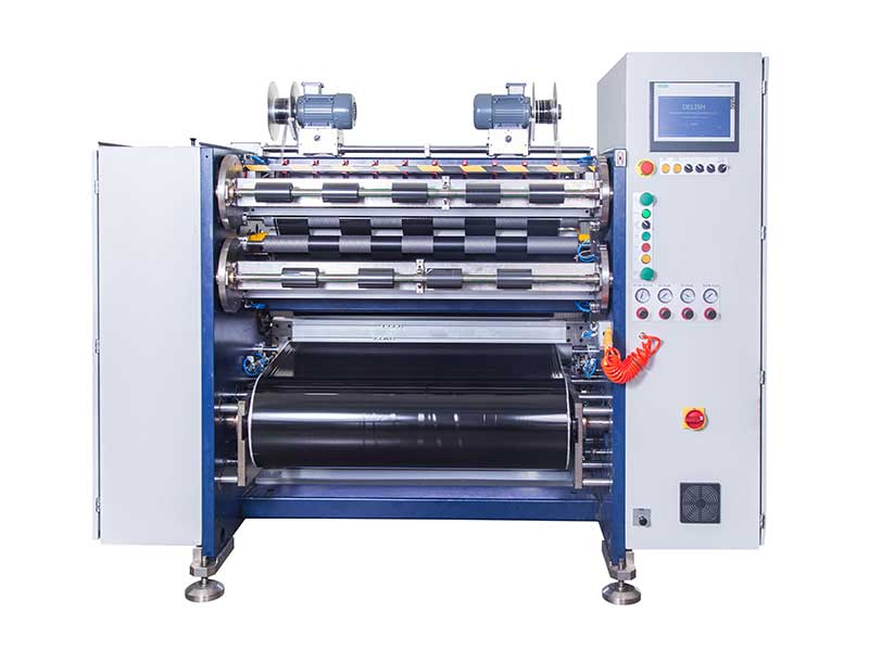
2. Upgrade of electrical and sensing systems: accurate perception and execution
1. Drive system upgrade
◦ Problem: AC asynchronous motor speed regulation performance is poor and torque response is slow, resulting in inaccurate tension control.
◦ Optimization Practices:
▪ Full servo drive system: the main traction, winding, unwinding, and cutting knives are all driven by servo motors.
▪ Advantages: Precise torque control, extremely fast dynamic response, and complex tension control algorithms can be implemented. The rewinding servo can directly control the torque and form a true closed-loop tension system.
2. Refinement of the sensing system
◦ Problems: Low sensor accuracy, poor anti-interference ability, and inaccurate feedback signal.
◦ Optimization Practices:
▪ High-resolution encoder: High-resolution absolute encoder is installed on the main traction and float rollers to accurately measure linear speed and roll position.
▪ Tension sensor: Choose a strain gauge tension sensor, match the range, and do a good job of signal shielding to avoid electromagnetic interference.
▪ Edge/Line Array CCD Correction System: Replace ultrasonic or photoelectric sensors to detect the edges of transparent or ultra-thin ribbons with high precision to achieve millisecond-level accurate correction.
▪ Machine vision inspection system: Add industrial cameras before winding to detect slitting quality (such as burrs, stains, broken bands) in real time, and automatically alarm or shut down.
3. Electrical cabinet and wiring specifications
◦ Problem: Poor heat dissipation, electromagnetic interference (EMI) leading to occasional equipment failures.
◦ Optimization Practices:
▪ Thermal management: Calculate the heat dissipation demand based on the total power consumption, and equip it with industrial air conditioners or heat exchangers to ensure stable temperature inside the cabinet.
▪ EMC design: power lines, encoder lines, and communication lines (such as EtherCAT) are routed separately, shielded cables are used, and grounding is standardized. Add input reactor and output DV/DT filter to suppress harmonics.
3. Control system and algorithm optimization: the brain and nerves of the device
This is the core of taking mechanical and electrical hardware capabilities to the extreme.
1. Core: Tension control algorithm
◦ Problem: PID parameters are cured and cannot adapt to the huge inertia changes brought about by the change of retraction and deceleration and acceleration process.
◦ Optimization Practices:
▪ Full closed-loop tension control: with tension sensor feedback as the core, it constitutes a PID closed loop.
▪ Taper tension control: When winding, as the coil diameter increases, the system automatically lowers the tension set value according to the preset curve (straight line, curve taper) to prevent the outer ribbon from squeezing the inner layer, causing wrinkles or deformation.
▪ Feedforward compensation: When the equipment accelerates or decelerates, a compensation torque is output to the retracting/unwinding servo in advance to offset the impact of the change of inertia on the tension. This requires the system to accurately calculate the moment of inertia under the current coil diameter.
▪ Adaptive PID: PID parameters can be automatically adjusted according to the roll diameter, running speed and other working conditions to maintain the optimal control effect.
2. Calculation of the diameter of the retracted and unloaded roll
◦ Issue: Inaccurate roll diameter calculations cause taper control and inertia feedforward to fail.
◦ Optimization Practices:
▪ Linear velocity integration method: Real-time integration calculation of the roll diameter is carried out through the pulse difference between the main traction shaft encoder and the retractor/unwinding reel encoder. This is the most precise method, but requires a high-resolution encoder.
▪ Cascading method: The length of the material is recorded by the meter counter, and the roll diameter is calculated in combination with the thickness of the material. This method requires known material thickness and no slippage.
3. Human-computer interaction (HMI) and data management
◦ Problems: Complex parameter settings, unclear fault information, and lack of production data traceability.
◦ Optimization Practices:
▪ Formula function: For ribbons of different materials and widths, preset tension, speed, knife distance and other parameters can be called with one click.
▪ Visual debugging: Real-time display of tension curve, speed curve, current coil diameter, PID output, etc., which is convenient for engineers to debug and diagnose.
▪ Fault diagnosis and prediction: Establish a detailed fault code base and record historical alarms. Predictive maintenance reminders are provided by analyzing data such as motor load and bearing vibration.
4. Systematic maintenance and management: long-term guarantee of reliability
1. Preventive maintenance plan
◦ Daily: clean carbon deposits and debris on knife holders and guide rollers; Check the pressure of the air source.
◦ Weekly: check whether the expansion of the expansion shaft is uniform; Check whether the bolts in key areas are loose.
◦ Monthly: check the wear of the blade, replace or sharpen the blade in time; Clean servo motor fan filter; Check the tension of the drive belt/timing belt.
◦ Every six months/year: professional dynamic balance calibration of spindles, guide rollers, etc.; Replace the lubricating oil of the reducer.
2. Spare parts and consumables management
◦ Establish a list of key spare parts (e.g., servo drives, blades, bearings, guiding sensors) to ensure inventory.
◦ Use original or certified high-quality consumables to avoid losing big due to small things.
3. Operator training
◦ Train operators on the correct loading and unloading process, parameter setting methods and daily inspection content.
◦ Train maintenance engineers on advanced diagnostics and parameter optimization.
Summary: Closed-loop logic for reliability improvement
Improving the reliability of ribbon slitting machine is a systematic project, which cannot be achieved by improving a single link. It follows a clear logical closed loop:
Precise Sensing (Advanced Sensors) → Intelligent Decision-Making (Advanced Control Algorithms) → Precise Execution (High Rigidity Machinery + Servo Drive) → Continuous Optimization (Data Traceability and Preventive Maintenance)
By building a solid foundation from the mechanical structure, achieving accurate perception and execution in electrical control, using intelligent algorithms to give equipment "wisdom", and finally forming a long-term guarantee through scientific operation and maintenance management, we can create a modern ribbon slitting machine with high speed, high precision, high reliability and low maintenance cost, and finally provide strong equipment support for enterprises to improve product quality, reduce production costs, and enhance market competitiveness.
This article starts from three core dimensions: speed, accuracy, and cost, helping you clarify your choice logic.
11. July, 2026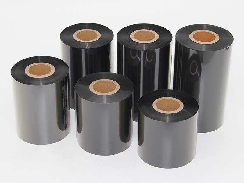
Tension is properly controlled, resulting in a flat and smooth product; When tension is out of control, burrs, broken bands, and layering follow one after another.
11. July, 2026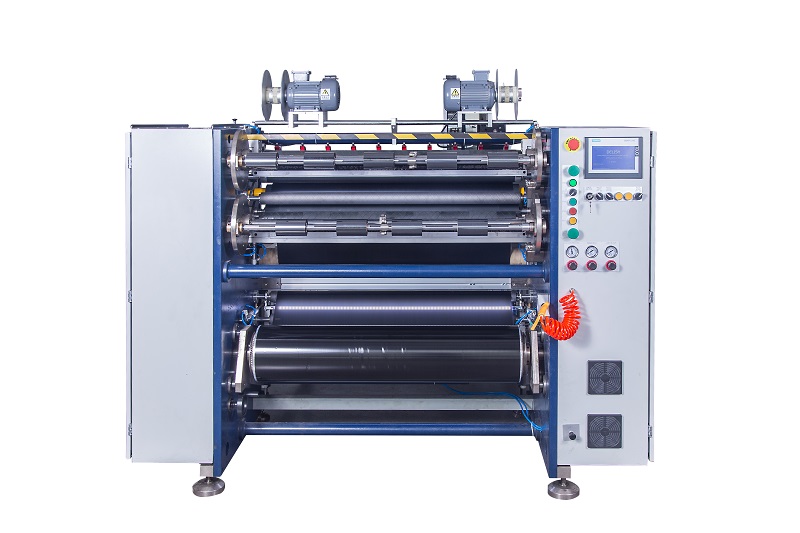
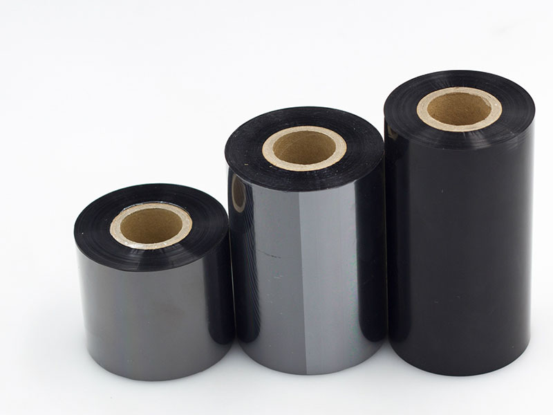
Usually, without replacing the main unit, improving overall efficiency by 20%-40% through the above 2-3 improvements is entirely achievable.
11. July, 2026Material saving is not simply "cutting a little less," but a systematic engineering system that spans equipment, processes, operations, and management.
09. July, 2026Behind this precision lies the result of a sophisticated system working together.
08. July, 2026


