
1. Introduction
The ribbon slitting machine is the core equipment for slitting wide busbars into customer-required specifications, and its operational stability directly affects product quality and delivery cycles. The ribbon substrate is typically PET film of 4.5~10μm, which is easy to stretch and wrinkle, making tension control and cutting precision the two core challenges during slitting. Frequent shutdowns not only reduce production efficiency but also cause considerable material waste. This article starts from common fault phenomena and systematically organizes their causes and repair plans.
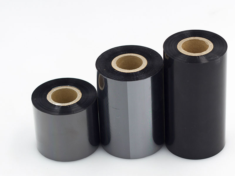
2. Six Common Faults and Repair Plans
Fault 1: Uneven slitting end face (burrs, saws, powder shedding)
Phenomenon description: After slitting, the ribbon edges are rough, wavy, or serrated, with whitish edges and a stringy feel, and even powder shedding.
Cause analysis:
1. Tool Factors: Blade wear or chipping are the most common causes. A blunt blade turns "shear" into "compression," causing edge stretching and deformation
2. Improper blade clearance: imbalance in the overlap between upper and lower blades (too large causes indentation, too small causes indentation, too small causes indentation), lateral clearance deviation
3. Tension fluctuations: Fluctuating tension causes the ribbon to drift at the edge, causing intermittent burrs
4. Static Interference: Electrostatic adsorption of dust generated by high-speed slitting, contaminating the edge and worsening trimming quality
Repair Plan:
• Replace the blade: replace immediately if wear or cracks are found; it is recommended to inspect once every shift; Cemented carbide inserts should be replaced every 100~150 hours of operation
• Adjust blade clearance: control the overlap between upper and lower blades at 0.01~0.03mm, maintain lateral clearance at 0.02~0.05mm, and calibrate using feeler gauge
• Tension system calibration: Check whether the tension sensor signal is stable and recalibrate the tension control system
• Install static elimination rods: Install AC-type static elimination rods at the roller to ensure the equipment's grounding resistance is less than 4Ω
Fault 2: Uneven winding (end face staggered layers, tower shape, daisy core)
Phenomenon description: The winding end face appears as a bell-shaped or tower-shaped staggered layer, or local raised "bars" or inner layer wrinkles.
Cause analysis:
1. Unreasonable tension taper: When the roll diameter increases, tension does not decrease, and the outer layer crushes the inner layer, forming a 'chrysanthemum core'
2. Mechanical parallelism deviation: The winding shaft is not parallel to the guide roller, or the tension force at both ends is inconsistent
3. Uneven pressure on the roller: If the pressure difference at both ends exceeds 0.05MPa, local bulging occurs
4. Correction system failure: sensor contamination or insensitive actuator operation
Repair Plan:
• Adjust tension taper: taper coefficient set to 0.3~0.5; initial tension 12N, end reduced to 8N (for example, 300mm outer diameter core)
• Parallelism calibration: Use a level to calibrate the parallelism between the winding shaft and the guide rail, with an error not exceeding 0.2mm/m
• Balanced pressure roller pressure: pressure difference at both ends controlled within 0.05MPa
• Clean the correction sensor: Wipe the photoelectric or ultrasonic sensor probe with alcohol to check whether the actuator operates sensitively
Fault 3: Ribbon breakage and loss of tension
Phenomenon description: Carbon belt suddenly breaks during operation, causing unplanned shutdown—statistics show that broken strips account for more than 60% of unplanned shutdowns.
Cause analysis:
1. Excessive tension setting: Excessive tension can directly stretch or even break the PET substrate
2. Foreign objects on the roller: Burrs, glue scale, or carbon powder clumping on the guide roller surface, scratching or rubbing the ribbon
3. Weak joints or incorrect tape threading: Insufficient strength of the worker joint or sharp angle friction in the tape threading path
Repair Plan:
• Adjust tension settings: reference tension for ribbons of different specifications — 3~5N for widths below 25mm, 6~10N for widths of 50mm
• Clean the rollers: Inspect all roller surfaces by touch, sand burrs with fine sandpaper, and wipe adhesives with alcohol
• Re-threading: Re-thread the tape according to the device's tape diagram to avoid sharp angle paths
• Joint inspection: Realign to ensure joint strength
Fault 4: Inconsistent slitting widths
Phenomenon description: In the same batch of products, the width deviation of each roll of carbon ribbon exceeds tolerance (usually required ± 0.3mm).
Cause analysis:
1. Blade mounting position is loose or locking mechanism fails
2. Insufficient dimensional accuracy of the spacer
3. Axial movement of the blade shaft exceeds the deviation
Repair Plan:
• After shutdown, measure the slitting width with a caliper to determine the fault location
• Check the cutter shaft locking nut and retighten it to the specified torque
• Measure the actual dimensions of the spacer and replace any deviations immediately
• Use a micrometer to detect the axial movement of the blade shaft; if it exceeds 0.02mm, adjust or replace the bearing
Fault 5: Abnormal rewinding hardness (too loose, too tight, wrinkling)
Phenomenon description: After winding, the ribbon core is too hard, too loose, or chrysanthemum heart-shaped wrinkles appear.
Cause analysis:
1. Unreasonable winding tension curve
2. Uneven or missing pressure on the rollers
3. Improper setting of the winding shaft taper
4. Mismatch between initial tension and running tension
Repair Plan:
• Check the taper tension controller settings; the taper value is usually between 20%~40%.
• Confirm the pressure balance at both ends of the pressure roller and test with a pressure gauge
• At startup, pre-roll at low speed (20~30m/min) for 2~3 turns, applying an initial tension 20% higher than the running tension to tighten the inner layer
• The core tube uses ABS or aluminum tubing with a wall thickness ≥ 3mm, with burr-free chamfers at both ends
Fault 6: Abnormal noise and operational shaking
Phenomenon description: The device emits periodic abnormal noises or sharp noises during operation, or noticeable body shaking.
Cause analysis:
1. Bearing damage (over 70% is caused by mechanical reasons)
2. Poor gear meshing or lack of oil
3. Belt slippage or wear
4. The guide roller is not parallel, and the blade shaft clearance is too large
Repair Plan:
• Audio Localization: Use a listening stick to locate the noise source; If the bearing is overheated or feels vibrating, replace it immediately
• Check the gearbox: Check the oil level and refill gear oil promptly if it falls below the lower limit
• Belt adjustment: Tighten or replace the belt appropriately when slipping; The middle part of the timing belt should have a deflection of 10~15mm
• No-load test: does not pass through the ribbon to idle to identify the source of vibration; Use a dial indicator to measure runout; control the guide roller runout within 0.05mm, and the spindle runout should not exceed 0.02mm

3. Complete Repair Process: From Inspection to Recovery
When a fault occurs, it is recommended to follow the standardized troubleshooting procedures below:
Step 1: Stop the machine and observe (static inspection)
First, stop the machine and visually inspect key areas—whether the blade is chipped, the bottom roller has any scratches, and the roller pass is free of foreign objects wrapped around. Check whether mechanical transmission components are stuck or loose.
Step two: Empty running test
Do not use ribbons or idle equipment; observe whether each roller rotates smoothly and listen for abnormal sounds. Initial identification indicates mechanical or material issues.
Step 3: Segment inspection
Disconnect the winding and unwinding linkages, test the unwinding braking performance and winding traction performance separately, and lock the fault to a specific section (unwinding section/slitting section/winding section).
Step 4: Trial Cutting Verification
Replace with a new blade for trial cutting of 200-meter master coils, running at 80% of normal speed. Observe the first 100 meters of the winding end face and check the cut; After the last 100 meters, observe changes in high-speed conditions and quickly eliminate tool issues.
Step 5: Parameter restoration and recording
If troubleshooting still does not resolve the issue, you can restore the parameters to factory backup values and re-debug. Establish a fault record ledger to record each fault phenomenon, cause, and handling method, forming an experience base.
4. Preventive maintenance system
Passive maintenance is not as good as proactive prevention. Systematic preventive maintenance can reduce unplanned downtime by more than 90%, with a finished product rate stable above 98%.
(1) Daily Maintenance (Performed by Operator)
| Project | Content | Standard |
| Clean the material route | Wipe all rollers and guide wheels with 95% alcohol | Removes toner powder and adhesive scale to prevent scratches and misalignment of the coating |
| Check the blade | and his eyes gazed at the blade's edge, whether it was cracked or chipped | Inspect every shift and replace immediately if abnormalities are found |
| Check the air pressure | Check the pressure gauge of the air source triple unit | Standard range: 0.5~0.7MPa |
| Emptying out accumulated water | Air filter drainage | Prevent moisture from entering the cylinder and causing corrosion |
(2) Weekly maintenance (performed by technicians)
• Deeply clean the drivetrain and check belt tension
• Calibration of tension sensor zero points (performed without film penetration)
• Check the airtightness of the reeling and unwinding reel; the runout of the reeling should be less than 0.05mm
• Clean old slip slip and add lithium-based grease
(3) Monthly maintenance
• Thoroughly check whether electrical terminals are loose and clean the electrical cabinet filter
• Check whether the coupling top wire is loose and whether the timing belt deflection is normal
• Check whether all cylinders operate smoothly and for any air leaks
(4) Quarterly/annual maintenance
• Replace worn bearings and calibrate equipment levelness
• Verify slitting width accuracy (tolerance ±0.3mm)
• Comprehensive motor performance inspection and inspection of circuit boards
(5) Establish a tool life ledger
It is recommended to establish a tool management archive to record the number of meters used after each grinding, and forcibly slitting with blunt blades is strictly prohibited. Ordinary white steel tools are lightly ground once per shift, and carbide knives are replaced after 100~150 hours of operation.
5. Special maintenance of the tension control system
Tension control accuracy is the lifeline of ribbon slitting quality and requires special attention.
Key checkpoints
1. Magnetic powder brake/clutch: Check whether the surface temperature is too high (hot to the touch, overheating). Overheating can cause the magnetic powder to sinter or demagnetize
2. Floating swing roller: Observe whether the swing roller is "breathing" near the set position—high-frequency jitter may be due to excessive PID gain or pressure fluctuations
3. Tension sensor: Check whether the value has reset to zero while stationary; if not, perform zero calibration
Parameter tuning principles
• Increase the ratio (P) for faster response; If oscillation occurs, increase integral (I) to eliminate static difference; If overshoot is severe, add the derivative (D) appropriately.
• The P-value in the magnetic powder clutch system should not be too high (response speed is much slower than that of servo systems).
6. Conclusion
The stable operation of the ribbon slitting machine is essentially the result of the synergy of mechanical precision, tension control, and tool condition. The core of daily maintenance can be summed up in eight words: clean, lubricate, adjust, and tighten.
Shifting maintenance thinking from "passive emergency repairs" to "proactive prevention"—establishing standardized inspection systems, implementing a management system of "fixed personnel, machines, and responsibilities," and recording equipment health records not only greatly reduces unplanned downtime losses but also extends equipment lifespan and ensures consistent high quality of slitted products. When encountering sudden faults, remember the principle of "observe first, judge later, then act," and most faults can be located and resolved within 15~30 minutes.
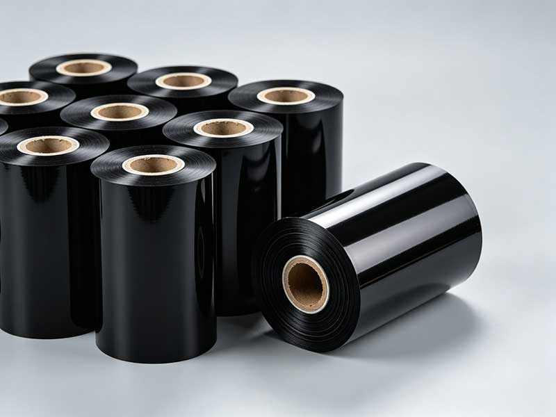
the key to choosing a model is not to pursue the "highest configuration," but to find a balance that matches your own business.
12. October, 2026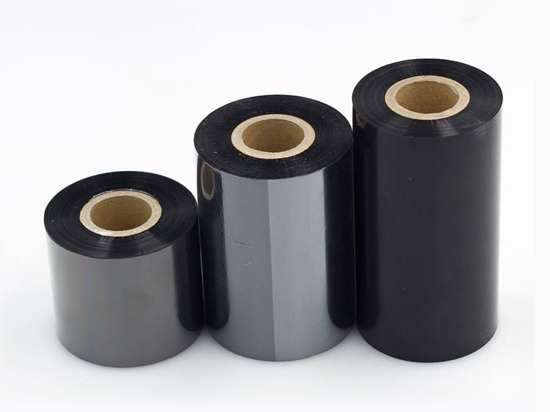
The coating formula, base film characteristics, and physical specifications of the ribbon directly affect the suitability and yield of the slitting machine.
09. October, 2026The core function of a ribbon slitting machine revolves around three dimensions: "precise cutting, stable rolling, and fast running."
09. October, 2026
This article starts from actual usage scenarios to outline a clear selection approach.
09. October, 2026The essence of uneven end faces in ribbon slitting machines is an external manifestation of subtle imbalances between tension, parallelism, correction, and tool condition.
05. October, 2026


 English
 Deutsch
 Français
 Español
 Português
 日本語
日本語 русский
 한국어
한국어 عربي
عربي ภาษาไทย
 Tiếng Việt
 Italiano