
Abstract
In the slitting process of thermal transfer ribbons, the substrate "edge-running" has long been a core problem in the industry, directly affecting yield and production efficiency. As a key technical solution to this problem, the correction system uses the core logic of "real-time sensor monitoring + dynamic algorithm correction + precise actuator adjustment" to form a closed-loop control system that enables online automatic correction of ribbon trajectories. This paper systematically explains the application practice of the correction system in high-speed ribbon slitting machines from the perspectives of system architecture, core component selection, key indicators, and development trends.
1. Introduction
Thermal transfer ribbons are core consumables in fields such as barcode printing and label printing. Their slitting precision directly determines print quality—whether the barcode is clear, the edges are neat, and whether the print head lifespan is affected. In the slitting process, the wide-width large-axis ribbon must be cut into small rolls of different widths according to customer requirements for use by end equipment. However, the ribbon substrate is usually PET film only 4.5~10 microns thick, which is extremely sensitive and prone to axial displacement during high-speed slitting due to uneven tension, uneven core, guide roll deviation, or static electricity, known as "edge run."
Minor misalignment may cause only a few millimeters of width loss, but severe edge runoff can lead to uneven ribbon edges, wrinkles, or even tearing, resulting in waste ranging from several meters to tens of meters, and at worst, the entire roll is scrapped. Traditional mechanical limit blocks or manual visual adjustments either cause hard contact scratching the coating or delayed response that cannot meet high-speed production demands, urgently requiring efficient and intelligent correction solutions.
2. Composition and Working Principle of the Correction System
Modern intelligent correction systems are based on the core logic of "real-time sensor monitoring + dynamic algorithm correction + precise actuator adjustment," forming a closed-loop control system.
Inspection stage: The correction sensor aligns with the slitted ribbon edge and continuously scans for position changes. The system uses correction sensors to detect the edge position of materials in real time and feeds the deviation signal back to the control center.
Decision-making stage: The position signals collected by the sensor are transmitted in real time to the industrial-grade controller, which has built-in PID or other adaptive algorithms that dynamically calculate the optimal correction instruction based on current offset, offset speed, and historical trends. Unlike traditional switch-based control, intelligent controllers can predict imminent offsets and make fine adjustments in advance to achieve "non-sensory correction."
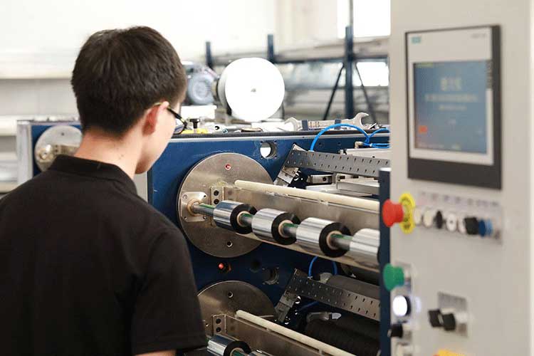
Execution stage: The controller sends instructions to drive the servo motor or electric cylinder, pushing the centering frame or winding mounting seat to move slightly laterally along the slide rod. For example, in a ribbon slitting machine correction system, the receiving motor is installed on the mounting base, which is slidably connected to the slide rod, and the driving mechanism drives the slide to achieve precise adjustment of the winding position. This smooth, continuous, and controllable movement guides the entire ribbon path to automatically align without touching the ribbon, without the need for shutdown or manual intervention.
3. Core components and key technologies
3.1 Selection of Correction Sensors
Sensors are the "eyes" of the correction system; their accuracy and response speed directly determine the system's performance ceiling. Current mainstream solutions include:
Ultrasonic sensor: Unaffected by ribbon color and transparency, can stably detect the edges of opaque, semi-transparent, and even highly transparent substrates, suitable for various materials including PET substrates.
Photoelectric sensors and CCD line array cameras: suitable for scenes with marked lines, with detection accuracy reaching ±0.1mm or even higher. Some high-end systems use dual CCD visual positioning systems, achieving subpixel-level accuracy detection through image processing algorithms, and feature adaptive edge tracking technology that automatically adjusts tracking parameters even when facing slight ribbon edge fluctuations. The dual-sensor infrared and CCD sensor solution can simultaneously detect PET substrate edges and identify ink coating patterns, with correction accuracy reaching ±0.1mm.
3.2 Actuators and Drive Methods
The actuator acts as the "hand" of the correction system; its accuracy and stability affect the correction effect. The servo motor-driven ball screw combined with pre-pressure double nuts eliminates reverse clearance, ensuring a positioning accuracy of ±0.02mm for the ribbon cable. Compared to pneumatic or conventional stepper motors, servo solutions respond faster and position more accurately, making them suitable for high-speed slitting scenarios. In a fully closed-loop configuration, a rotary encoder or magnetic grating scale is installed at the shaft end to provide real-time feedback position signals, further improving control accuracy.
3.3 Coordination of Correction and Tension Control
The correction system does not operate in isolation; it is tightly coupled with the tension control system. Belt deviation during slitting is often causal to tension fluctuations: unstable tension causes material expansion and contraction deformation, which in turn triggers deviation; If deviated, it causes uneven winding ends and exacerbates local tension abnormalities. Therefore, modern high-precision slitting machines typically integrate the centering system with the floating swing roller closed-loop tension control system, performing the first coarse correction at the slitting blade outlet and the second fine correction before winding, forming a "straightening + tension" coordinated control architecture.

4. Key Performance Indicators
The core metrics for measuring the performance of the correction system mainly include:
Correction accuracy: Static conditions can reach ±1μm, dynamic conditions ±3μm. In industry-leading solutions, the servo system-driven correction mechanism can control dynamic correction accuracy within ±0.1mm.
Response speed: The sensor sampling frequency must reach above 1kHz, and the response time for controllers and actuators is usually within 20ms.
Practical Effect: Using intelligent offset correction slitting machines can reduce the defect rate caused by edge running from 3%~5% in traditional methods to below 0.2%, while ensuring stable operation of the slitting machine at the highest design speed without frequent stops for adjustments.
5. Development Trends
As ribbon slitting evolves toward higher speeds and narrower widths, straightening systems face new technical challenges. Predictive correction control has become an important trend, meaning that correction mechanisms are adjusted in advance based on material movement trajectory prediction models, rather than relying solely on post-event corrections. Multi-mode composite correction technology automatically switches sensor operating modes for different materials (transparent PET, high-gloss black ribbons, etc.), enhancing system adaptability. In addition, the correction system is deeply integrated with the equipment management platform, recording correction parameters and operational data of different types of ribbons to establish a "medical record card" for equipment, assisting process optimization and fault diagnosis.
6. Conclusion
The application of the high-speed ribbon slitting machine correction system essentially represents a shift from "passive remediation" to "active control" production mode. Based on precision sensors, intelligent algorithms, and high-performance actuators, it transforms the traditional problem of edge running into a controllable variable. In practical applications, correction accuracy, response speed, and system synergy are core dimensions for evaluating the quality of solutions, while the significant reduction in scrap rate and increased effective equipment operating time are the best proof of its value. For enterprises pursuing micron-level slitting accuracy and efficient production, building high-performance correction systems has become an indispensable technical path.
The essence of uneven end faces in ribbon slitting machines is an external manifestation of subtle imbalances between tension, parallelism, correction, and tool condition.
05. October, 2026To solve this problem, a systematic inspection is needed from four dimensions: tension control, mechanical precision, auxiliary systems, and operating standards.
05. October, 2026The first watershed in choosing a model isn't speed or brand, but rather — which type of ribbon do you mainly cut?
23. September, 2026When asking suppliers the following seven questions, the quality of the answers is far more valuable than the numbers on the parameter table.
21. September, 2026
This guide explains what buyers need to know about each parameter—not just the numbers, but the practical implications for production quality, material compatibility, and total cost of ownership.
18. September, 2026


 English
 Deutsch
 Français
 Español
 Português
 日本語
日本語 русский
 한국어
한국어 عربي
عربي ภาษาไทย
 Tiếng Việt
 Italiano